FEA Simulation & Mould Flow Analysis Service — Engineering Confidence Before You Build
Advanced Structural FEA, CFD, Mould Flow, and Topology Optimisation to validate performance and eliminate manufacturing risks — before a single rupee is spent on tooling or production.
What Is FEA Simulation & Mould Flow Analysis?
Two related but distinct simulation disciplines that answer different questions about a part — before you commit to tooling or production.
FEA Simulation
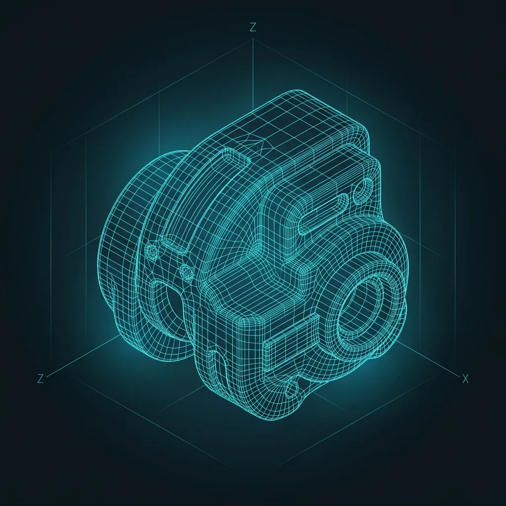
Finite Element Analysis breaks a 3D CAD model into thousands of small elements and calculates how the part behaves under real-world loads — structural stress, deformation, thermal gradients, and fatigue over its service life. It answers: will this part survive?
Mould Flow Analysis
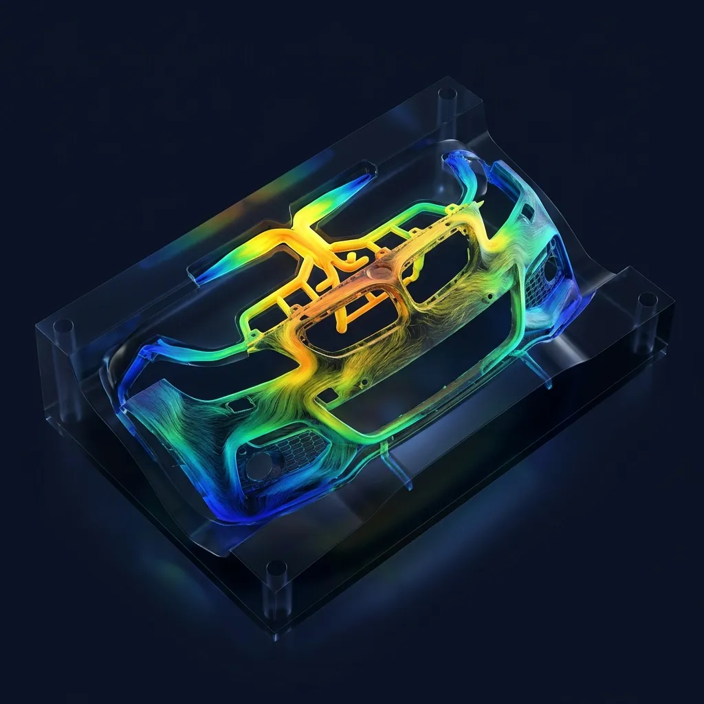
Mould flow (Moldflow/Moldex3D) analysis simulates how molten plastic fills, packs, and cools inside an injection mould cavity — predicting fill time, weld lines, warpage, and shrinkage. It answers a different question: will this part mould correctly and hold its shape?
How They Work Together
For a plastic component, both studies typically run through the same simulate-before-build pipeline — CAD upload through boundary conditions, meshing and solver setup, simulation run, engineering interpretation, and design recommendations — with mould-specific checks like gate location and cooling-channel layout folded into the meshing and boundary-condition stages rather than run as a separate step count.
FEA Simulation vs. Physical Prototype Testing
A physical prototype only confirms whether one build survived one test; FEA predicts stress, deformation, and failure across the full range of load cases before a single mould or fixture is cut.
In practice, teams reach a 98% first-time success rate by simulating early and reserving physical prototypes for final confirmation rather than initial design exploration — see how this plays out on our CAE services page.
Build It Wrong Once or Simulate It Right First
What We Simulate for You
Our Simulation Services — In Detail
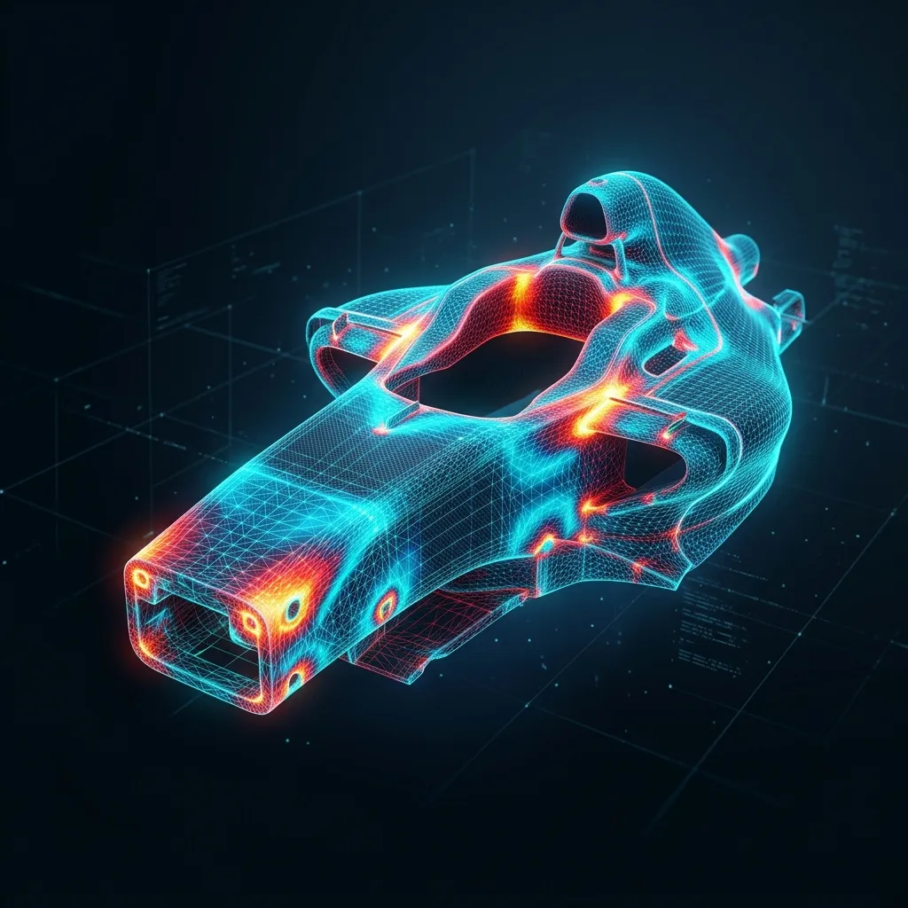
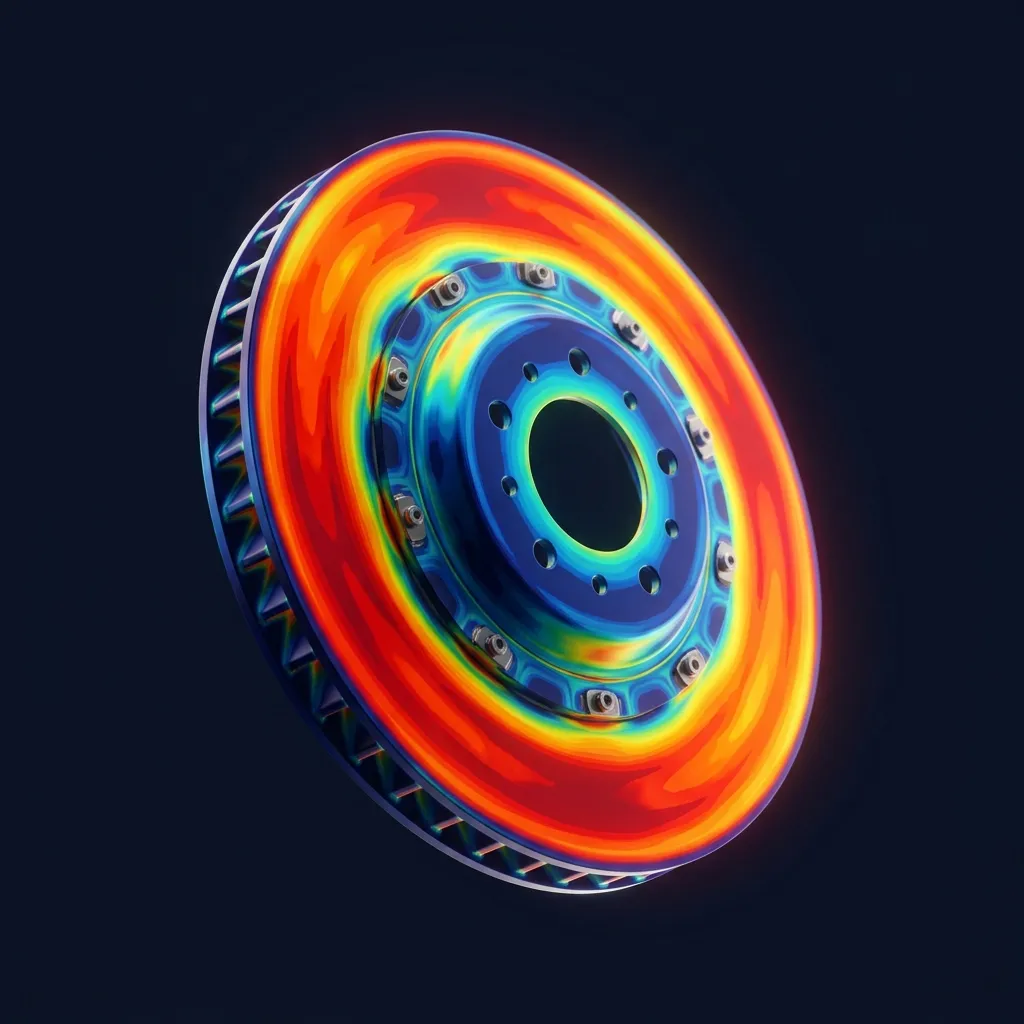
Ensure mechanical integrity under real-world thermal and physical loads before manufacturing. Linear, non-linear, and thermally coupled analyses on complex assemblies.
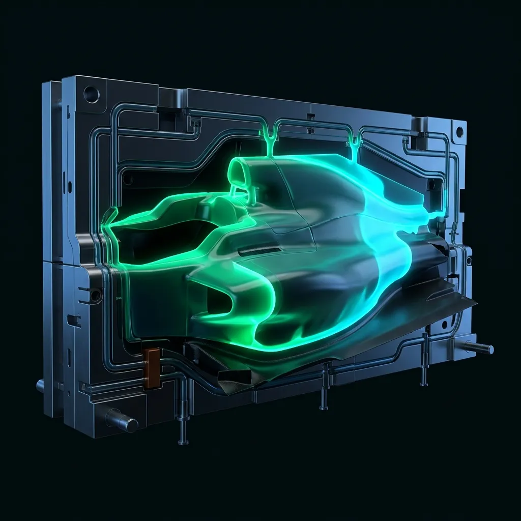
Optimize gating design, eliminate warpage, and guarantee complete cavity fill before cutting steel. Moldflow and Moldex3D simulations for every injection cycle parameter.
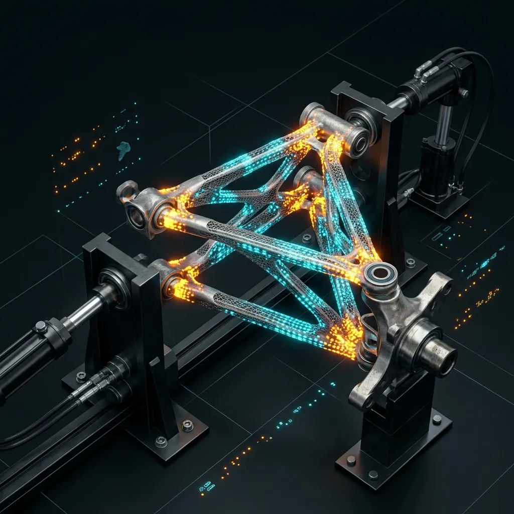
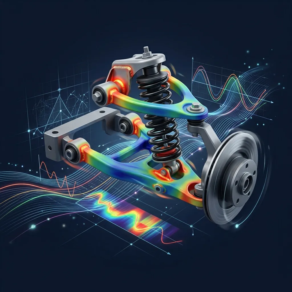
Predict lifecycle under cyclic loading and identify failure zones before field deployment. Our durability studies replace years of bench testing with validated predictions.
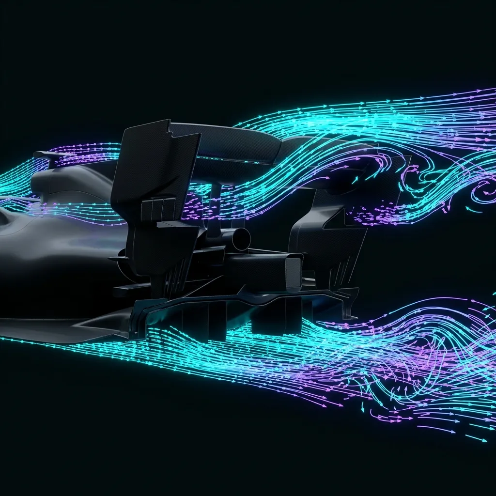
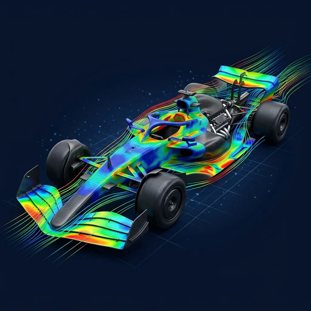
Analyze fluid and gas flow across complex geometries — from cooling channels to aerodynamic surfaces. Actionable optimization reports, not just visualizations.
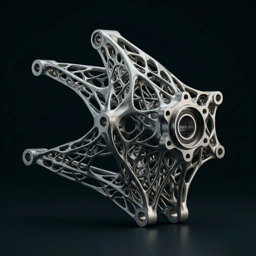
Redesign parts for minimum weight with maximum structural performance — trusted in aerospace, automotive, and medical device sectors for significant mass reduction.
From CAD Model to Engineering Decision
What Your Team Receives



Why Indian Manufacturers Outsource Simulation to APJ 3D
Engineering Judgement
Beyond raw solver outputs — domain physics insight into non-linear loads, thermal coupling & fatigue limits.
Dedicated CAE Team
Senior simulation engineers proficient in ANSYS Mechanical, Abaqus, Moldflow, Moldex3D & HyperMesh.
4000+ Projects Experience
Proven track record solving complex structural, flow, and plastic moulding challenges across India.
Multi-Industry Expertise
Tailored simulation workflows for Automotive, Aerospace, Defence, SPM Machinery & Consumer Goods.
What is FEA Simulation & Mould Flow Analysis Service?
CAE Simulation (FEA & CFD) is the numerical modeling of physical systems to predict structural stress, thermal dissipation, fluid flow, crashworthiness, and dynamic fatigue life under real-world operational loads.
When to Select This Service
Choose CAE simulation during early product development to virtually validate design integrity, optimize part weight, verify safety factors, and eliminate physical prototype failure risks before committing to production tooling.
Technical Capabilities & Verification Standards
Verified engineering parameters, hardware precision, and compliance benchmarks applied across all deliverables.
| Engineering Parameter | APJ 3D Capability & Precision Range | Compliance Standard / Verification |
|---|---|---|
| Simulation Disciplines | Linear/Non-Linear Structural FEA, Thermal Analysis, CFD Fluid Dynamics, Crash & Impact, Fatigue & Durability, NVH | ISO 9001 / NAFEMS Validated Procedures |
| Solvers & Software | ANSYS Mechanical, Abaqus, Altair HyperWorks/OptiStruct, Moldflow, OpenFOAM, LS-DYNA | High-Performance Computing (HPC) Clusters |
| Material Models | Elastic-Plastic metals, Hyperelastic rubbers, Composites, Viscoelastic polymers, Temperature-dependent curves | Tested Material Property Databases |
| Mould Flow Capabilities | Fill time, injection pressure, weld line prediction, sink marks, cooling circuit efficiency, volumetric shrinkage & warpage | Autodesk Moldflow Insight Validated |
| Deliverables | Comprehensive Engineering Reports, Von Mises Stress Plots, Factor of Safety (FoS) Maps, Deformation Animations, Optimization STEPs | Actionable Design Recommendation Summaries |
| Model Scale | From precision micromixers and plastic clips up to full vehicle chassis and industrial equipment weldments | Multi-Million Degree-of-Freedom Meshes |
| Turnaround Time | 3 to 7 business days for standard FEA/CFD studies; 24–48h for urgent gate location & fill checks | Dedicated Senior CAE Analysts |
Frequently Asked Questions
What information is required to start an FEA or CFD simulation?
What information is required to start an FEA or CFD simulation?
How do you validate the accuracy of simulation results?
How do you validate the accuracy of simulation results?
How can Moldflow simulation save tooling costs for plastic parts?
How can Moldflow simulation save tooling costs for plastic parts?
Can you optimize parts for lightweighting and material reduction?
Can you optimize parts for lightweighting and material reduction?
What is included in the final simulation report?
What is included in the final simulation report?
Need Accurate Simulation Results for Your Components?
Tell us your component geometry, material, and load conditions. Our CAE team will recommend the right simulation approach and validate performance before you invest in tooling.